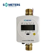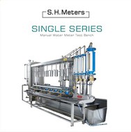


Hebei Shanghong Meters Technology Co., Ltd. is one of the leading manufacturers and suppliers of ultrasonic water meter test bench used to ultrasonic water meters in China. If you're going to wholesale high quality ultrasonic water meter test bench used to ultrasonic water meters, welcome to get pricelist and quotation from our factory.
Ultrasonic water meter test bench used to ultrasonic water meters
According to the current standards and measurement verification regulations of cold water meters, hot water meters and heat meters, a newly developed multi-functional measurement and detection device integrating cold and hot liquid flow. At the same time, it can carry out the measurement and detection of cold water meters, hot water meters and heat meters.
The design technology of the device is novel, advanced, and highly automated. The calculation, detection and control software is at the leading level in the same industry in the country, and it is simple, flexible and convenient to operate. The device uses video camera and M-BUS to read the flow indicator of the meter under inspection, avoids human error, and achieves accurate and reliable measurement and detection results. It has the remarkable characteristics of high work efficiency and excellent calculation performance.
Piston Water Meter Verification Device
1. Basic Information About the Device
Device flow range | (2-8000)L/h |
Device uncertainty | ≤0.2% (k=2) |
Pressure range | 0- 1.6MPa |
Ambient temperature | 15-25℃ |
Relative humidity | (45% -75%) |
Atmospheric pressure | (86-106)kpa |
Working pressure | 0- 1.6MPa |
Power supply voltage | 400V±5%, 50HZ |
Air source pressure | (3.5-6)bar |
Equipment power | water pump 1.8KW, piston 3KW, heating 6KW |
Number of inspection meters | Ultrasonic meters (DN15: 10 pcs, DN20: 8 pcs, DN25: 6 pcs) |
Equipment size | length, width, and height (5800 mm *1500 mm *2500mm) |

2. Device Composition
This device is composed of a water source system, a piston system, a clamp meter pipeline, a flow adjustment device, a standard device system, a software control system, and a data acquisition system;

2.1 Water Source System
Water pump or piston: the highest flow rate is 8m³/h, using frequency converter control, the software can set different frequencies
Airbag pressure stabilizing tank: used to stabilize the pressure of the pipeline system. The flow rate of Q3 and above uses a water pump for water supply. It is also used to detect bubbles before flushing.
Water tank: 304 stainless steel, the bottom of the water tank is equipped with a liquid level sensor, the software system can collect the current level of the water tank, is equipped with an electric heating device, and the water temperature control accuracy is ±1℃.
2.2 Piston System

The standard cumulative flow of the piston device is the product of the piston's internal cross-sectional area and the piston displacement in the time period. Therefore, the accurate measurement of the piston displacement is one of the key factors to reduce the uncertainty of the device. The piston cylinder diameter is 215mm, and a temperature and pressure sensor is installed at the piston outlet to compensate for the error of the piston cylinder diameter. In order to improve the accuracy of displacement measurement, this device uses a grating ruler to measure the displacement of the piston. The output signal of the grating ruler is an AB quadrature signal with an accuracy of 1us.
Piston volume | 22L |
Applicable flow range | 2L-2500L |
Resolution | resolution 0.036ml |
Drive motor | Panasonic servo motor |
Grating ruler | German ELGO/24V/1us |
Temperature sensor | PT100/A level |
Pressure sensor | 0-1.6Mpa, 0.5% accuracy |
2.3 Clamp Meter Pipeline
The meter inspection pipeline is composed of the meter clamping device, pipeline, on-off valve and so on. The clamping device for the tested meter is also called the meter clamp, which can adjust the distance according to the length of the meter, and can clamp various tested meters freely. This program clamp meter adopts an external cylinder type clamping mechanism, which effectively prevents air leakage caused by damage to the sealing ring caused by excessive use time. The test pipeline is set to meet the clamping requirements of the tested meter. The clamp table of the device uses three optical axes as positioning points. The optical axis is mounted on a stainless steel fixed plate used for wire cutting. The coaxiality is good. The front and rear straight pipe sections are made of POM material. The coefficient of thermal expansion and contraction is very small. The slider adopts numerical control. The machining center is processed at one time.

2.4 Flow Regulation Control:
The device is equipped with two flow point pipelines, and two electromagnetic flowmeters are used as flow indicating devices. Below 250L, DN2.5 caliber electromagnetic display is used, and above 250L, DN25 electromagnetic display is used. Pistons are used to provide flow below 500L, and water pumps are used to provide flow above 500L. Equipped with a pneumatic regulating valve. PLC adopts PID control mode. According to the feedback of electromagnetic flowmeter, the opening of pneumatic regulating valve is controlled to adjust the set flow.
2.5 Standard System
The device standard device adopts a combination of piston and electronic scale. The device uses piston as the standard device by default <=500l. the="" piston="" can="" provide="" accurate="" instantaneous="" flow.="" you="" also="" use="" a="" high-speed="" counter="" to="" collect="" displacement="" pulse="" of="" grating="" ruler="" achieve="" standard="" volume="" measurement.="" when="">500L, the device uses 150KG/6000E electronic scale as the standard device.
2.6 Software Control System
The control system is mainly composed of industrial computer, Siemens S7-200smart system, servo motor, grating ruler, various temperature and pressure sensors, pneumatic ball valve, platform software, etc. The industrial computer has strong anti-interference performance, which can make the verification process more stable and reliable; PLC and servo motors adopt internationally renowned brands with high precision and high reliability, and the control and data processing software are written in accordance with the relevant national verification regulations.
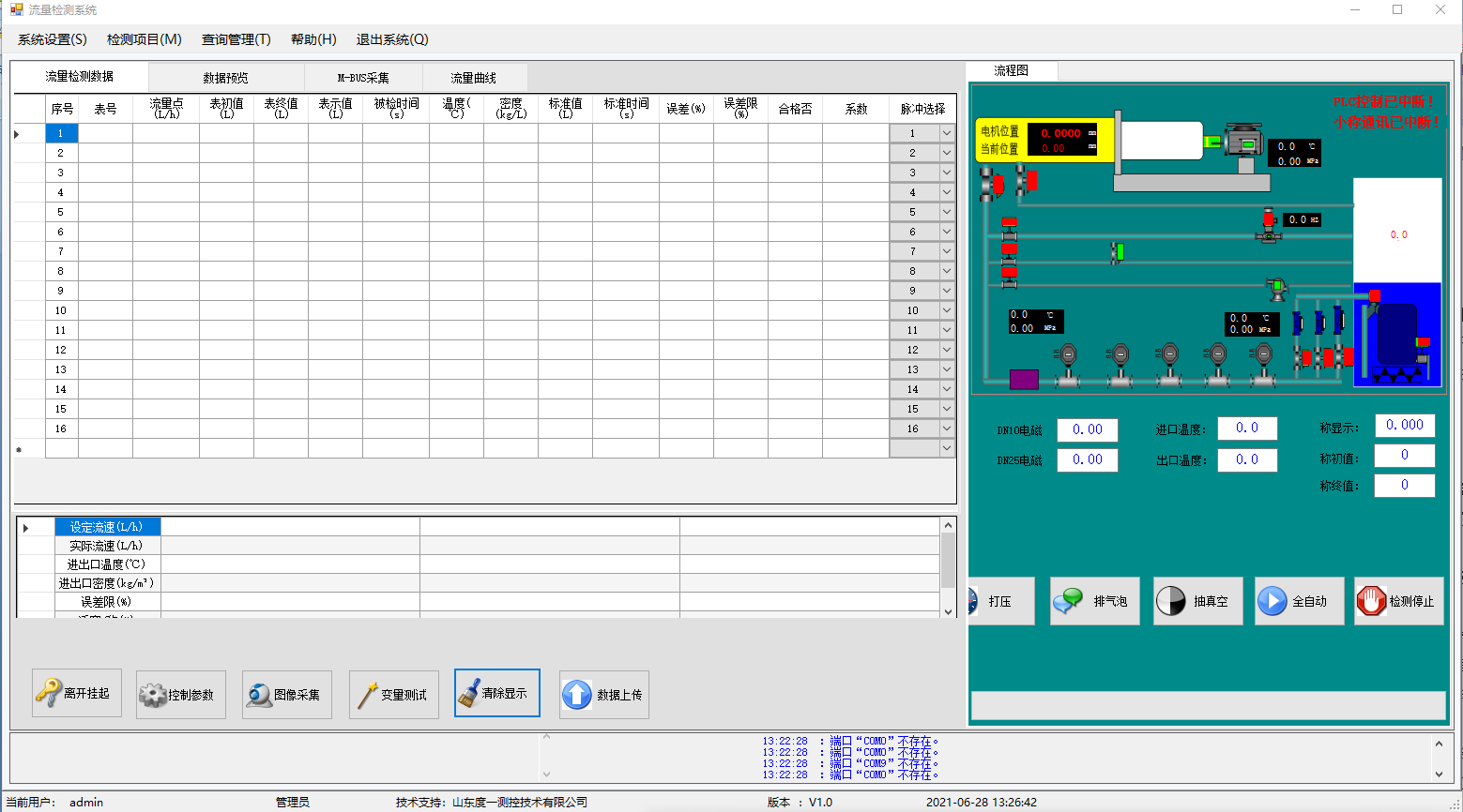
The sensors mainly include temperature sensor and pressure sensor, which are located at the inlet and outlet of the pipeline and the water outlet of the piston. They are respectively used to measure the temperature and pressure of the liquid, and then transmit the information to the PLC and software system in time. The control system has many protections and sound and light alarms, such as low air pressure alarm, low water tank level alarm, meter not in place alarm, piston over temperature alarm, piston over pressure alarm, piston limit alarm, etc.
In this device, the temperature measurement range of the temperature sensor is (0~100)ºC, and the accuracy level is A; the pressure measurement range of the pressure sensor is (0~1.6) MPa, and the accuracy level is not less than 0.5%.
The software of this device is written in Visual studio C#, using Microsoft ACCESS database, the detection process can be written into the database, and the user can modify the control process according to different permissions.
After the detection, the error data is saved to the database, and the user can query the detection error data at any time.
The software communicates with PLC, electronic scale, high-speed counter, etc. through the RS232 serial port.
The software communicates with the tested water meter through a serial port. The water meter can use infrared, MBUS, RS485, NFC and other signals, but it needs to be converted to an RS232 interface to connect to an industrial computer. The water meter manufacturer also needs to provide a detailed communication protocol. The software communication protocol definition is written into the database, and the user can modify some control codes or return parameter definitions without changing the structure frame.
3. Device Configuration Selection Table
Main standard device | Piston + electronic scale |
Flow range | 0.002-8[m³/h] |
Water pump | 69H/8 m³/h |
Working pressure | 10[bar] |
Length of the tested meter | DN15 (165mm) 14 pcs |
DN20(195mm) 12 pcs | |
DN25 (225mm) 10 pcs | |
Piston specifications | Volume 22L/resolution 0.036ml/pressure PN16/Panasonic servo drive |
Electronic scale | 120KG/6000E |
Weighing container | 120L |
Electromagnetic flowmeter | AXG/DN2.5+DN25, Japan Commutator DN25 |
Commutator | DN25 |
Temperature sensor | PT100, accuracy class A, installed at the inlet and outlet |
Pressure sensor | accuracy of 0.5%, installed at the inlet and outlet |
Test method | start-stop method + commutator method |
Standard signal interface | Pulse / MBUS / RS485/Image acquisition/Laser sensor |
Equipment power | 380V, 50Hz, 3 Phase 5Wire Power, 10KW(peak power) |
Hydropower | The user provides AC400V three-phase five-wire power supply/pure water/6bar pressure |
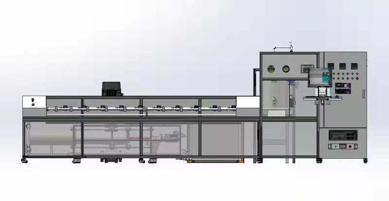
DN15~50 Automatic Water Meter Verification Regulations
When verifying the water meter, first check whether the verification device rotameter and switch, measuring cylinder valve switch, pressure gauge, thermometer, control buttons, etc. are normal and intact.
(1) Open the two-position four-way clip meter control valve to clamp the tested water meter horizontally in the device according to the direction of water flow, close the bypass drain valve of the flow regulating valve, and open the water inlet ball valve.
(2) Open the regulating valve of the large flow meter first and then the regulating valve of the small flow meter to remove the air in the water meter and pipeline (note that the regulating valve should be opened slowly to avoid damage to the flow meter), and then close one by one.
(3) Open the bypass drain valve, make the pointer of the water meter point to "0" or a certain scale, and record the scale. After putting clean water (30 seconds after changing from continuous flow to dripping water), close the water valve. Turn on and adjust the flow rate of the flowmeter to the boundary flow point, and wait until the value displayed in the working counter reaches the specified measurement value. Immediately close the regulating valve; record the indicated value of the scale of the working machine after the indicated water level in the working counter is static.
(4) Turn on and adjust the flow rate of the flowmeter to the nominal flow point, and repeat the operation of (3).
(5) Slowly open the minimum flow regulating valve to increase the flow rate slowly. When the triangular (circular) pointer starts to rotate continuously and evenly with the naked eye, record the indicated value of the gauge as the sensitive value of the water meter (starting flow rate).
(6) Determine whether the tested water meter is qualified according to the verification requirements, and close the water inlet valve.
(7) After the verification of the water meter is completed, open the bypass water discharge valve to drain the residual pressure in the pipeline, and open the clip to control the unloading of the meter.
After the meter calibration is finished, the water inlet ball valve should be closed, and the remaining water in the standard container, rotameter and pipeline should be drained.
Performance characteristics of automatic water meter verification device
1. Intuitive and credible
The automatic water meter verification device is based on the most commonly used "volumetric method verification" in my country, and uses a camera instead of human eyes to read the pointer of the water meter. The automatic recognition accuracy reaches 1/3 of the minimum score of the water meter, and the automatic recognition rate is greater than 90%.
2. Advanced science
Integrating electronics, imaging, and mechanical technologies, it is easy to operate, easy to use and maintain.
3. Accurate and reliable
It adopts photoelectric induction signal, which is sensitive to the change of water level, produces stable water level pulse signal, and has excellent anti-interference performance. The computer adopts a variety of fast mathematical algorithms to ensure the real-time and reliability of image recognition, eliminate human errors, and improve the accuracy of the device.
4. Artificial intelligence
The verification device realizes the automatic reading of the flow rate of the tested water meter and the standard container, the automatic switching of the flow rate, and the automatic calculation of the error after the verification is completed and the printing of the report. The entire verification process is fully automated.
5. Strong data management functionality
The computer verification software equipped with the verification device automatically calculates according to the regulations and draws the verification conclusion. It can save all the water meter verification data and has complete database functions such as verification record query, statistics, and printing.
The automatic water meter verification device is easy to operate, stable and reliable, improves verification efficiency and avoids human error. Greatly reduce the measurement disputes caused by the accuracy of water meters in the past, and further improve the water meter testing center of our company.

Factors Affecting Water Meter Verification Results
1. Water Temperature
The verification water temperature should be (0.1~30) ℃, which meets the measurement performance requirements. Too low water temperature will affect the measurement performance of the water meter, especially the measurement performance of the minimum flow Q1 and the starting flow, that is, the water meter displays slowly.
2. Water Pressure
According to the verification regulations, the pressure at the inlet of the water meter during the verification shall not exceed the maximum allowable working pressure of the water meter to be tested, and the outlet pressure of the water meter shall not be less than 0.03MPa.
3. The water pressure fluctuates, and the water contains air bubbles
In the water meter volume verification, the flow range can be controlled by the glass rotameter, and the gas is discharged before the verification. The fluctuation of the water pressure and the air bubbles in the water caused by the turbulence, vortex, and deflow of the water meter in the pipeline All will produce positive deviations to the verification results of the water meter under small flow rates.
Error Control
1. The verification environment needs to meet the requirements
Only in the environment specified in the verification regulations, the corresponding verification method can ensure the accuracy of the verification results. We can control the ambient temperature through the air conditioner, and the water temperature will gradually rise during the verification process. If it is necessary to lower the water temperature, we can inject tap water with a lower temperature into the circulating pool.
2. Regular maintenance
If the verification device is used for a long time, the components will be worn out and aging, which will cause changes in the measurement characteristics of the measurement standard. Therefore, we must regularly maintain the verification device to prevent possible introduction Error factors were discovered in time. If a part fails, it must be repaired or replaced in time.
3. Improve the technical level of the testing staff
Verification personnel must pass professional training and examinations, obtain relevant employment certificates, and work with certificates. It is necessary to be proficient in the relevant policies of quality technical supervision and metrological verification, and to keep improving the verification technology. While theoretically studying, the technical level of metrology verification is continuously improved, and the experience is continuously summarized in the daily water meter verification process, so as to closely link theoretical knowledge with practical work and improve the skill level of the verification personnel.
Hot Tags: ultrasonic water meter test bench used to ultrasonic water meters, manufacturers, wholesale, pricelist, quotation